
I've been collecting information on the Futurliners for close to ten years, with the intention of someday building a model of one. In October of 1998 I visited NATMUS in Auburn, Indiana and found out they had a Futurliner, and that it was about to picked up by a group of volunteers who would soon begin restoring it to it's original glory. I immediately volunteered myself to build a model for the museum.
|
| This CAD drawing was done as to aid in building the model of the Futurliner. It took about three months of my spare time to complete the drawing. Click on the image to view a large version of the drawing. |
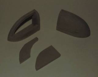
| Here I've cut some blocks of Renshape to approximate size for the rear end. After gluing them together with CA adhesive, I mill, carve and sand to final shape. |
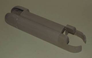
| The lower portion of the front end was created in the same fashion as the rear. The side and "spine" were milled from solid blocks of Renshape. |
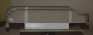
| The center portion of the rear end has been added at this point, and a sample of the "multi-cove" lower skin is also in place to give a better idea of the full height. Remember there will be a full perimeter bumper below the cove as well. |
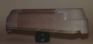
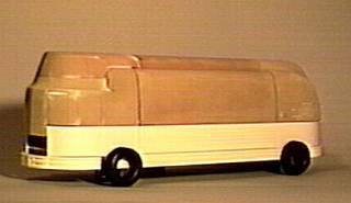
| The rest of the cab is added, and the model is starting to take shape here.
Click here for additional views at this stage. |
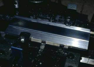
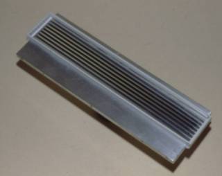
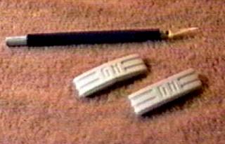
| Here I am making a master pattern for the "multi-cove" lower skin. After determining the correct radius and spacing, I used a ball end mill to cut properly spaced "coves" in to a piece of flat aluminum stock. Next I used a regular end mill to cut a .125" wide by .060" deep pocket around the cove area. |
| Styrene strip stock was used to make a .250" high box around the cove pattern area as shown here. Enough two part RTV silicone mold material to fill the box was mixed, poured in to the box and allowed to cure. |
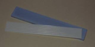
| After the RTV silicone had cured the mold was carefully removed from the box and coated with mold release. Two part urethane casting resin was mixed, poured into the mold and allowed to cure. This picture shows the RTV mold (light blue) and the finished cove casting (white). The finished casting is flexible enough that it will bend and conform to the curvature of the front and rear of the model. It will take six casting to cover the entire model. |
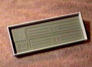
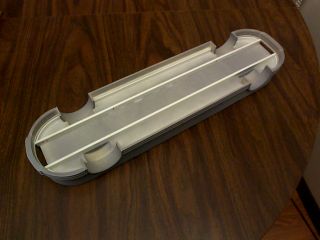
| This is the master pattern for the front and rear bumper skins. It was milled from Renshape using a Roland MDX-3 desktop CNC. An RTV silicone mold was made from this pattern in the same fashion as the cove mold was made. Urethane castings for the bumper skins were then made in the RTV mold. |
| The bumper skin castings were then formed and glued to bumpers made of Renshape. The rest of the front and rear bumpers were made in the same fashion. |
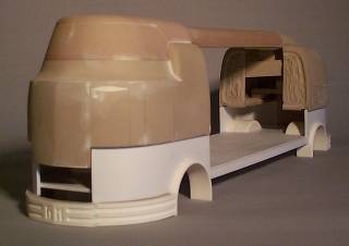
| The middle section of the body is nearing completion. It has been constructed from
various thicknesses of sheet styrene. This mid-section will provide the backing for the attachment
of the cove sheets created previously. This mid-section will eventually rest directly on the chassis.
The nearly completed front, rear and side bumpers have been temporarily attached to the mid-section
for these pictures. Since the wheel wells have yet to be cut into the mid-section the tires have been
propped up against the model for the time being.
Click here for another view at this stage. |
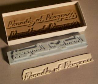
| The master pattern milled from Renshape, the RTV silicone mold, and a finished casting of the Parade of Progress script which will go on the sides of the model |
| The middle section of the body now has wheel wells and fender lips. The wheel wells
and fender lips are cast resin duplicates of patterns milled from Renshape.
Click here for a slightly different angle where you can see the front bumper a little better. |
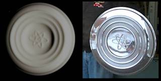
| A 1/24 scale hubcap on the left and it's full scale counterpart on the right. The scale hubcap is cast in polyurethane resin. The outer portion of the master was turned from aluminum while the center detail was engraved in styrene using the MDX-3. |
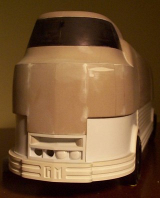
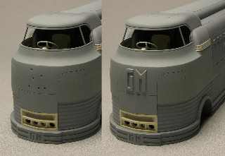
| The grill and headlight patterns are pretty much completed now. Here's a picture of them positioned in place on the front of the model. |
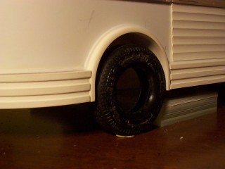
| A close up of the forward wheel well with a tire in position. |
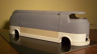
| A lot of work has been done on the internal areas that doesn't show in this picture. A large amount of material has been removed from the inside of the upper body to make room for the driver and passenger areas. The "multi-cove" lower skin has now been installed around the entire mid-section of the body. |
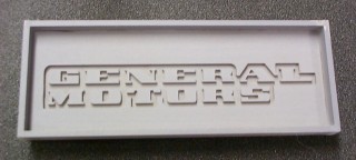
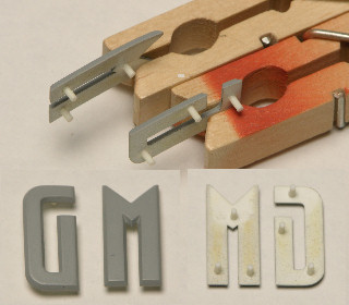
| A master pattern milled from Renshape, of the General Motors lettering for the side of the Futurliner door |
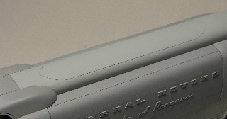
| The General Motors and Parade of Progress lettering installed on the side of the Futurliner door. |
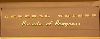
| A close up of the lettering on the door. |
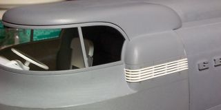
| Some of the panel lines have now been scribed into the cab and the vertical frames that separate the windshield from the vent windows have been added. The GM is just a paper cutout to check the size. |
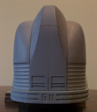
| Panel lines have been scribed for the rear doors and the tail light and license plate frames have been added. |
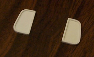
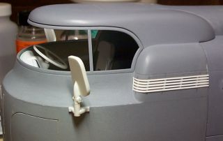
| Work has begun on the rear view mirrors. The rest of the supports have yet to be made. |
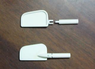
| The mirrors shown with partially completed pivots. |
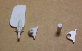
| The mirror support bases were made from a piece of styrene rod and 0.080 styrene sheet as shown on the right. The assembled base is shown on the left, next to the finished mirror and pivot. |
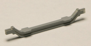
| The frame rails are in place. The crossmembers need to be added next. |
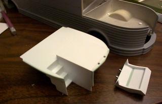
| I have now begun work on the interior of the cab. Here you can see the floor and entry steps of the driver and passenger compartment. The dash board is also visible. Most of the interior design has been done with a CAD program. The individual parts were then cut from sheet styrene with using the MDX-3. After a little bit of sanding for final fit the parts were glued together into their various sub-assemblies. |
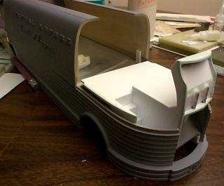
| The floor, steps and dash in position on the front of the Futurliner. The exterior of the cab fits over this assembly. |
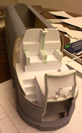
| The passenger seats have been assembled. They are shown in position at the rear wall of the Futurliner cab. Barely visible over the top of the dash is the steering column support. |
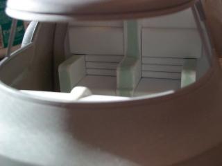
| With the cab exterior in place, here is a view of the passenger seats through the front windshield. |
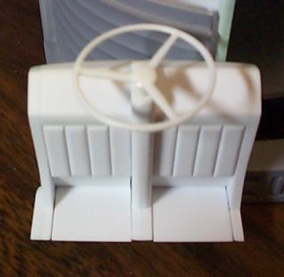
| The dash and steering column nears completion. |
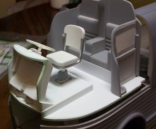
| The cab interior with the drivers seat in place. The side walls of the passenger area are also in place. |
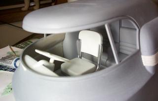
| Another look at the interior through the windshield. |
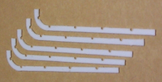
| I've started work on the side grills. Here are five pieces cut from 0.020 sheet styrene that will become the horizontal grill bars. |
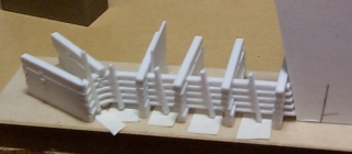
| The grill bars in an assembly jig. The jig holds the grill bars at the correct spacing of 0.030 inches. |
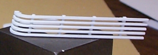
| An assembled grill. |
| The opening for the side grill has been cut into the cab. |
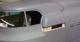
| The side grill in position on the cab side. |
| The mirror and side grill in position on the cab side. |
| The GM letters for the front of the cab were made by laminating layers of 0.020 thick styrene sheet. After cutting the letters to the correct shape, each layer of styrene was hand formed to match the contour of the cab before the layers were glued together. The edges of the letters were tapered and any imperfections were filled. |
| The letter locations were marked on the cab, then locating holes were drilled through the cab. The letters were positioned temporarily using masking tape while the mounting locations were drilled into the back of the letters using the holes in the cab as guides. Styrene locating pegs were then added to the backs of the letters. |
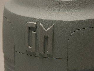
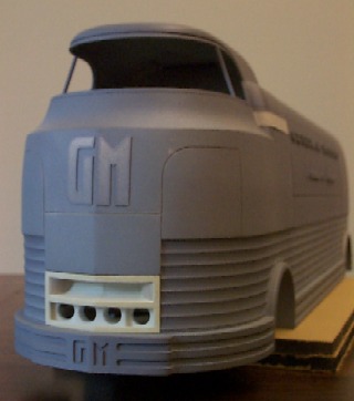
| The GM letters in position on the cab front. |
| The light bar outline has now been scribed into the roof of the Futurliner. |
| I have started to fabricate the front axle. It is made from several laminations of various thicknesses of styrene. |

| This is the artwork I'm working on for the raised letters on the tire sidewalls. I plan to use the artwork to photo-etch the letters so I can add them to the tires. |
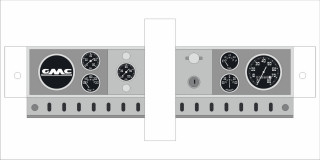
| This is the dash board layout I've been working on. The dash board details will probably be a combination of photo-etch and decals. |